- 您现在的位置:买卖IC网 > Sheet目录341 > MAX8834ZEWP+T (Maxim Integrated)IC LED DRIVR BCKLGT FLASH 20-WLP
�� �
�
�MAX8834Y/MAX8834Z�
�Adaptive� Step-Up� Converters�
�with� 1.5A� Flash� Driver�
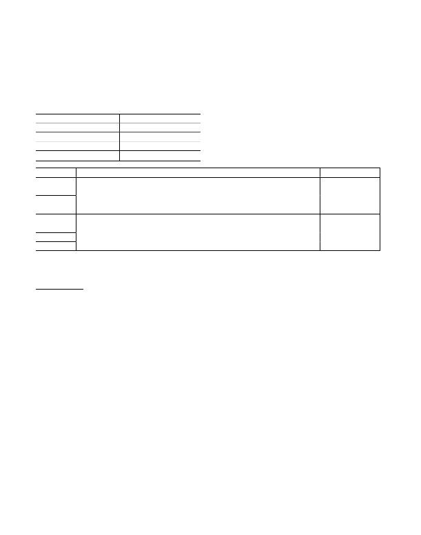
�Table� 18.� CHIP_ID2�
�This� register� contains� the� die� type� dash� number� (0� =� plain)� and� mask� revision� level.�
�REGISTER� NAME�
�Address�
�Reset� Value�
�Type�
�Special� Features�
�CHIP_ID2�
�0x1B�
�N/A�
�Read�
�—�
�BIT�
�NAME�
�DESCRIPTION�
�DEFAULT� VALUE�
�B7� (MSB)�
�B6�
�B5�
�DASH�
�BCD� Character� representing� dash� number�
�—�
�B4�
�B3�
�B2�
�B1�
�MASK_REV�
�BCD� Character� representing� die� revision�
�—�
�B0� (LSB)�
�Note:� This� register� value� is� fixed� in� metal.�
�Applications� Information�
�Inductor� Selection�
�See� Table� 19� for� a� list� of� recommended� inductors.� To�
�prevent� core� saturation,� ensure� that� the� inductor� satura-�
�tion� current� rating� exceeds� the� peak� inductor� current�
�for� the� application.� Calculate� the� worst-case� peak�
�inductor� current� as� follows:�
�most� situations,� but� a� 4.7μF� ceramic� capacitor� is�
�acceptable� for� lower� load� currents.�
�Compensation� Network� Selection�
�The� step-up� converter� is� compensated� for� stability�
�through� an� external� compensation� network� from� COMP�
�to� AGND.� See� Table� 20� for� recommended� compensa-�
�tion� networks.�
�I� PEAK� =�
�V� OUT� � I� OUT (MAX )�
�0� .� 9� � V� IN� (� MIN� )�
�+�
�V� IN� (� MIN� )�
�2� � f� SW� � L�
�PCB� Layout�
�Due� to� fast-switching� waveforms� and� high-current�
�paths,� careful� PCB� layout� is� required.� Connect� AGND,�
�FGND,� and� PGND� directly� to� the� ground� plane.� The� IN�
�where� f� SW� is� the� switching� frequency.�
�Capacitor� Selection�
�Bypass� IN� to� AGND� and� PGND� with� a� ceramic� capaci-�
�tor.� Ceramic� capacitors� with� X5R� and� X7R� dielectrics� are�
�recommended� for� their� low� ESR� and� tighter� tolerances�
�over� wide� temperature� ranges.� Place� the� capacitor� as�
�close� as� possible� to� the� IC.� The� recommended� minimum�
�value� for� the� input� capacitor� is� 10μF;� however,� larger�
�value� capacitors� can� be� used� to� reduce� input� ripple� at�
�the� expense� of� size� and� higher� cost.�
�The� output� capacitance� required� depends� on� the� out-�
�put� current.� A� 10μF� ceramic� capacitor� works� well� in�
�Maxim� Integrated�
�bypass� capacitor� should� be� placed� as� close� as� possi-�
�ble� to� the� IC.� R� COMP� and� C� COMP� should� be� connected�
�between� COMP� and� AGND� as� close� as� possible� to� the�
�IC.� Minimize� trace� lengths� between� the� IC� and� the�
�inductor,� the� input� capacitor,� and� the� output� capacitor;�
�keep� these� traces� short,� direct,� and� wide.� The� ground�
�connections� of� C� IN� and� C� OUT� should� be� as� close�
�together� as� possible� and� connected� to� PGND.� The�
�traces� from� the� input� to� the� inductor� and� from� the� out-�
�put� capacitor� to� the� LEDs� may� be� longer.� Figure� 21�
�illustrates� an� example� PCB� layout� and� routing� scheme.�
�Refer� to� the� MAX8834Y/MAX8834Z� Evaluation� Kit� for� a�
�PCB� layout� example.�
�39�
�发布紧急采购,3分钟左右您将得到回复。
相关PDF资料
MAX8855EVKIT+
KIT EVAL FOR MAX8855
MAX8879ETG+T
IC LED DRVR WT/RGB BCKLGT 24TQFN
MAX8901BETA+TCH8
IC LED DRIVER WHITE BCKLGT 8TDFN
MAX8930EWJ+T
IC LED DRVR WT/RGB BCKLGT 49WLP
MAXQ2000-KIT
EVAL KIT FOR MAXQ2000
MAXQ610-KIT#
EVALUATION KIT FOR MAXQ610
MB2146-401-01A
KIT STARTER F2MC-8FX 3V
MB2146-401-03A
KIT STARTER F2MC-8FX 5V
相关代理商/技术参数
MAX8836ZEREEE+T
功能描述:电流型 PWM 控制器 1.2A PWM Step-Down Converter RoHS:否 制造商:Texas Instruments 开关频率:27 KHz 上升时间: 下降时间: 工作电源电压:6 V to 15 V 工作电源电流:1.5 mA 输出端数量:1 最大工作温度:+ 105 C 安装风格:SMD/SMT 封装 / 箱体:TSSOP-14
MAX8836ZEWEEE+
制造商:Rochester Electronics LLC 功能描述: 制造商:Maxim Integrated Products 功能描述:
MAX8836ZEWEEE+T
制造商:Maxim Integrated Products 功能描述:
MAX883C/D
功能描述:低压差稳压器 - LDO RoHS:否 制造商:Texas Instruments 最大输入电压:36 V 输出电压:1.4 V to 20.5 V 回动电压(最大值):307 mV 输出电流:1 A 负载调节:0.3 % 输出端数量: 输出类型:Fixed 最大工作温度:+ 125 C 安装风格:SMD/SMT 封装 / 箱体:VQFN-20
MAX883C/D DIE
制造商:Maxim Integrated Products 功能描述:
MAX883CPA
功能描述:低压差稳压器 - LDO 5/3.3/AdjV 200mA Linear Regulator RoHS:否 制造商:Texas Instruments 最大输入电压:36 V 输出电压:1.4 V to 20.5 V 回动电压(最大值):307 mV 输出电流:1 A 负载调节:0.3 % 输出端数量: 输出类型:Fixed 最大工作温度:+ 125 C 安装风格:SMD/SMT 封装 / 箱体:VQFN-20
MAX883CPA+
功能描述:低压差稳压器 - LDO 5/3.3/AdjV 200mA Linear Regulator RoHS:否 制造商:Texas Instruments 最大输入电压:36 V 输出电压:1.4 V to 20.5 V 回动电压(最大值):307 mV 输出电流:1 A 负载调节:0.3 % 输出端数量: 输出类型:Fixed 最大工作温度:+ 125 C 安装风格:SMD/SMT 封装 / 箱体:VQFN-20
MAX883CSA
功能描述:低压差稳压器 - LDO 5/3.3/AdjV 200mA Linear Regulator RoHS:否 制造商:Texas Instruments 最大输入电压:36 V 输出电压:1.4 V to 20.5 V 回动电压(最大值):307 mV 输出电流:1 A 负载调节:0.3 % 输出端数量: 输出类型:Fixed 最大工作温度:+ 125 C 安装风格:SMD/SMT 封装 / 箱体:VQFN-20